Introduction

Dosing pots are required in order to feed liquid chemicals such as corrosion inhibitors into closed systems.
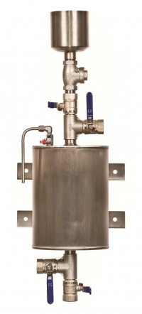
The dosing pots consist of a mild steel vessel with inlet (return) and outlet (flow) valves, a drain valve and a filling valve. A steel tundish, air release valve, wall mounting brackets and a non-return valve.
Dosing pots can also be supplied without the valves, and air release valve if requested.
Installation
It is important that the dosing pots are fitted correctly in to the system to allow rapid chemical feed. This is best achieved by connecting across the main flow and return pipework. Ideally the flow connection should be made on to the bottom of the dosing pot, and the return the top.
The dosing pot is designed for the conditions stated on the name plate, the system into which the dosing pot is installed should have adequate protection to ensure the dosing pot is operated within these limits at all times
We are now manufacturing all our chemical dosing pots so they can be installed either left or right handed for ease of installation purposes. Floor stands are also available upon request.
Operation
- Isolate pot: close all valves
- Drain pot: open valves A and D
- Charge pot: close valve D and introduce solution via valve A (tundish)
- Expel air :open air vent until solution appears
- Inject treatment: close valve A fully and open valves B and C
- The dosing pot may reach temperatures up to 120 degrees centigrade. Protection or warnings should be applied to ensure that personnel do not come into contact with the pot so as to avoid burns
- A check valve is to be installed to prevent accidental scolding and chemical saturation (blow back) of personnel operating the dosing pot
Maintenance
After long-term use the valves may require replacement. Periodic inspection should be conducted on the dosing pot in particular checking for corrosion wear. l mm corrosion allowance is provided for in the design. If corrosion is found to be greater than 1 mm the dosing pot should be taken out of use.
Specification
Stainless Steel
Welded to BS EN 287
All dosing pots that are designed to PD 5500:2000 category 3 (C E marked) have the following Maximum Working pressures:
- # 14 bar-3.5 litres to 6 litres inclusive
- # 10 bar- 10 litre to 20 litres inclusive
- # 8 bar-25 litres
Dosing pots that are not designed to the above are available which have max. working pressure of 14 bar throughout the range (3.5 litre to 25 litre).
Dosing Pots Sizes (litres)
- 3.5
- 5
- 6
- 10
- 11
- 13.5
- 15
- 16
- 18
- 20
- 25
Can also be made to order in sizes up to 50 litres
Pipeline Equipment
- Copper Expansion Bellows
- Axial & Articulated Expansion Joints
- Flexible Connectors For Pumps & Equipment
- Microbubble Air & Dirt Separators
- Chemical Dosing Pots
- Water Sample Coolers
- Magnetic Low Velocity / Loss Headers
- Fancoil Hoses & QRCs
- Inertia Base, Spring Anti-vibration Mounts & Spring Hangers
- Buffer Vessels - Horizontal & Vertical
- Vacuum Degassers
- Anchors & Expansion Joint Guides
